What elements go in the model, and what is the level of development of those elements?
Industry Language
There is a lot of confusion in the industry on how to request a Building Information Model, or BIM model for short. Some may know exactly what they need and others may have just been told to get a BIM model for a project. Either way, the two most important aspects to understand when requesting a BIM model is the difference between Scope of Work and LOD (i.e. Level of Development or Design).
Scope of Work
At Existing Conditions, we have worked on practically every building type imaginable, and our clients include building owners, architects, engineers, interior designers, historical societies, and more. Needless to say, every project is different. The one thing that all our projects have in common is a clearly-defined Scope of Work. Our proposals are custom-made for every project to make sure we get our clients exactly what they need. This is why it's important to understand how to read our Scope of Work page.
Some of our clients only need Floor Plans. Other clients require a more developed Model, which might include Exterior Elevations and RCP information. And sometimes our clients will ask us to include MEP information in the Model, understanding the added time and expense required to build MEP elements. These are only a few of the Deliverables we offer, and we can mix-and-match our deliverables to suit the needs of your project.
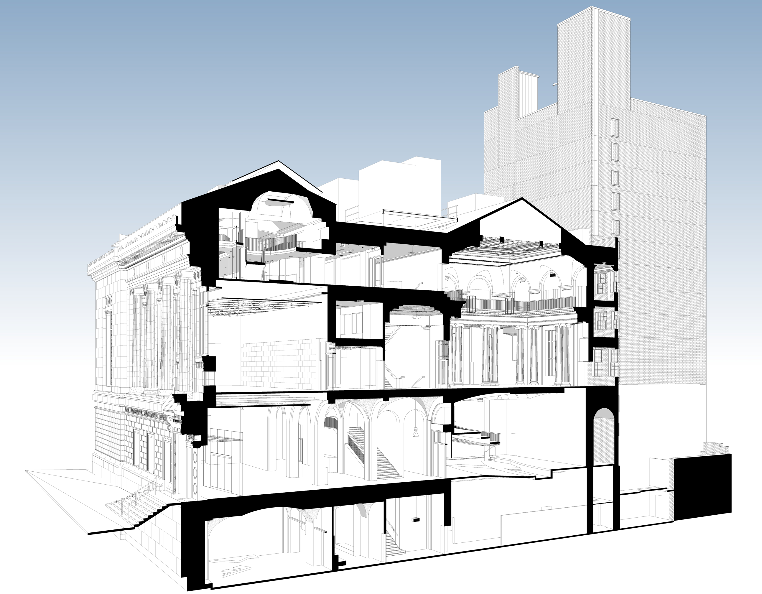
Example of a model which included Exterior Elevations, Floor Plans, and RCPs
Although the laser scanners we deploy measure everything within line-of-sight, our modeling scope will always be limited to those Elements in those Views which are listed in the Scope of Work of our proposal.
For more information, check out this article: 3D Point Cloud v Model.
For our clients who use 2D CAD this is an obvious distinction, but sometimes new clients who do not understand the process may ask for a "complete BIM model". This is not a useful term, because it does not specify what will, or will not, be included. For example, a BIM Model could include; parametric Room data, mechanical equipment maintenance schedules, or thermal property information, but it would be unreasonable to expect this information to be included. Our expert Sales consultants will work with you to make sure that the Elements you need in the Model will be included.
LOD (Level of Development/Design)
Level of development (LOD) is a set of specifications that gives professionals in the building industry the power to document, articulate, and specify the content of BIM effectively and clearly. Serving as an industry standard, LOD specifications allow architects, engineers, and other professionals to clearly communicate with each other about the reliability of information associated with elements in a model. This allows for faster, more efficient project execution. LOD is also used as a measure of the level of service required – it requires less labor to produce a rudimentary model at LOD 100 versus a more detailed LOD 300 model.
Below are the LOD levels of development (and estimated corresponding project phase*), as defined by the AIA Digital Practice Documents Guide:
LOD 100 - Concept Design
Model Elements may be graphically represented in the Model with a symbol or other generic representation.
LOD 200 - Schematic Design
Model Elements are generically and graphically represented within the Model with approximate quantity, size, shape, location, and orientation.
LOD 300 - Design Development
Model Elements are graphically represented within the Model with measurable quantity, size, shape, location, and orientation.
LOD 350 - Construction Documentation
Model Elements are graphically represented within the Model with measurable quantity, size, shape, location, orientation, and interfaces with adjacent or dependent Model Elements.
LOD 400 - Fabrication & Assembly
Model Elements are graphically represented within the Model with detail sufficient for fabrication, assembly, and installation.
LOD 500 - As-Built
Model Elements are graphical representions of existing or as-constructed condition developed through a combination of observation, field verification, or interpolation. The level of accuracy whall be noted or attached to the Model Element.
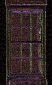
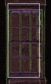
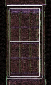
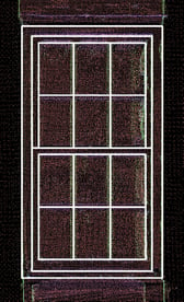
Point Cloud of Window LOD 100 LOD 200 LOD 300
Existing Condition's Approach for LOD & Scope of Work
Our Models at Existing Conditions are typically LOD 300, meaning that the Model Elements are graphically represented within the Model as specific objects in terms of quantity, size, shape, location, and orientation. Non-graphic information, such as fabrication, detailing information, type, or function is not attached to a LOD 300 Model. For most of our clients, this is more than enough information for their needs. And for those that need more detail, it's simply a matter of letting our team know early, in order to ensure that our work meets your expectations. Keep in mind that LOD refers to the level of development to which a single element within the Model has been brought. It does not determine what elements are or aren't included within the Model.
This is why we place most of our emphasis on the Scope of Work for a project and not the LOD. The Scope of Work is where you outline what elements will and won't be included within the Model, and in which Views those elements will be developed. After those elements and views are defined, then we can discuss what LOD is needed for different elements if it would be different than our standards LOD 300.
Please reach out to one of our team members to discuss your project today. They can help you navigate the scope of work for your next project to make sure you get exactly what you need at a great price.
*Note: project phases may not necessarily correspond with these LODs as listed. For more information, consult the Project Phases section of The AIA Digital Practice Documents Guide.
If you'd like to learn more, please visit our website, check out our portfolio, or contact us to connect with a member of our team.