As-Built Drawings to Reduce Rework and Improve Coordination
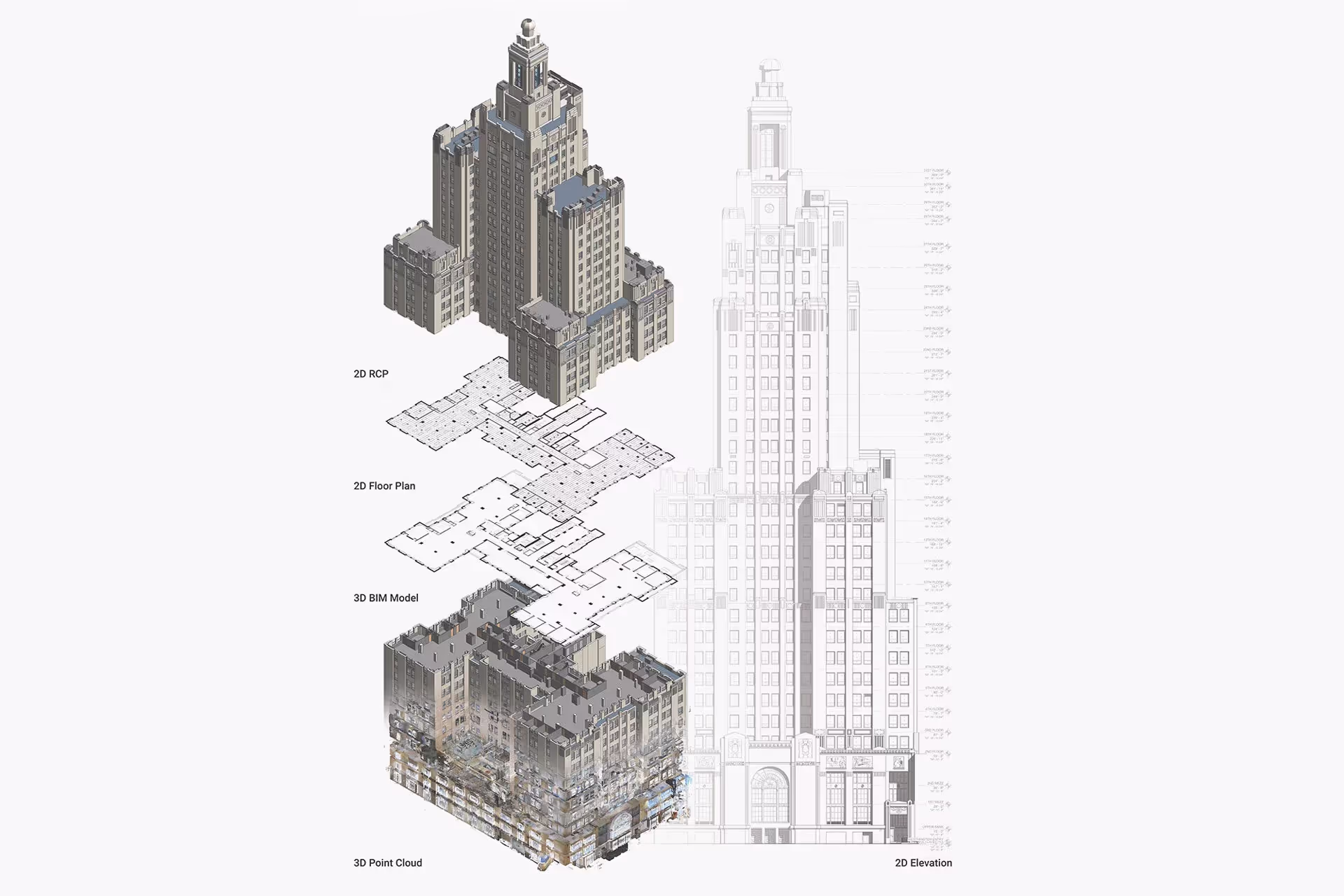
Existing Conditions delivers accurate 2D as‑built drawings for architecture, engineering, and construction projects. Our Project Managers deploy terrestrial LiDAR laser scanners to capture exact structural and MEP geometries, coordinates, and layouts of your building with 2-4mm accuracy.
Our Mapping & Modeling Team converts registered point clouds into project specific 2D CAD drawings and optional 3D BIM models at your preferred level of detail to help you make informed decisions and minimize errors.
Existing Conditions as-built drawing services help you:
- Understand the building’s layout, dimensions, and materials with millimeter-level accuracy
- Reference precise floor plans, sections, elevations, details, and RCPs
- Communicate project requirements and design intent
- Ensure that the design complies with zoning, codes, and safety regulations by basing calculations and clearances on verified existing conditions rather than assumptions
- Coordinate across trades to minimize conflicts or clashes
- Support future renovations, repairs, and upgrades
.avif)
Accurate As‑Built Building Records for Renovations & Maintenance
%20(1).avif)


What Types of 2D CAD Drawings Does Existing Conditions Create?
Site Plans
A site plan, sometimes referred to as a plot plan, is the graphic representation of all existing site conditions. The site plan shows the full layout of the project. It includes where buildings, paving, utilities, and terrain features are located, all in one view.
Floor Plans
A floor plan shows room layout and spatial relationships with walls, doors, windows, stairs, fixtures, and furniture tied to grid and level datums for precise coordination across trades. Dimensions, tags, and schedules communicate sizes, clearances, and quantities. They support design, retrofit, and field verification.
Interior Elevations
Interior elevations are 2D drawings that show the interior of a building from various angles. They show the size and shape of a building. They also show the placement of windows, doors, and other features. The elevation callouts and keynotes align with floor plan references to enable direct cross‑checks in reviews and on-site.
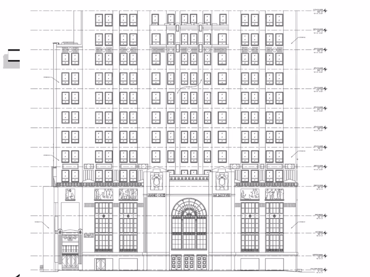
Exterior Elevations
Exterior elevation drawings are used to show how a building looks from the outside. They document the outline of a building in detail, including the placement of windows, doors, curtain walls, porches, decks, loading docks, and more. Design professionals request as-built exterior elevations to help them see how the building levels stack and where windows and doors align.
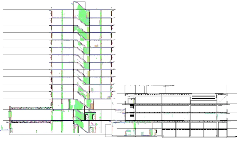
Sections or Cross Sections
Sections are 2D drawings that show the cutaway view of a building, structure, or object, disclosing details of the internal structure.
Details
Details are 2D drawings that show a specific element of a building, structure, or object enlarged in more detail. The element is scaled for dimensioning and clarification purposes.
Isometric Drawings
An isometric drawing is a representation of a 3D object drawn on a flat plane that mainly contains 2D coordinates – the x and y axes. Although it uses a 2D coordinate system, it gives the illusion that a 3D system is being used. Isometric drawings are made by tilting the viewing angle to 30 degrees for all sides in the 2D plane.
Mechanical and Electrical Drawings
These drawings show important details about the plumbing, HVAC, electrical, and other mechanical systems (MEP) in a building. Standardized schedules and notes help with installation, coordination, and inspection. This applies to plumbing, HVAC, electrical, and low-voltage systems.
Reflected Ceiling Plan
A reflected ceiling plan displays ceiling height and materials. It includes level changes, sprinklers, smoke detectors, and more. The dimensions and tags help with trade coordination.
Roof Plan
A roof plan documents roof geometry, ridges, eaves/rakes/parapets, skylights, vents, chimneys, and mechanical curbs for construction coordination and review.
Contour Maps
Contour mapping produces a plan (bird’s‑eye) view that depicts elevation changes across a floor or surface using lines at fixed intervals to show grade and relief.
Deformation Maps
Deformation maps depict a built surface’s topography, showing floor or surface elevations at specific points with clarity and detail.
BOMA Measurements
BOMA (Building Owners and Managers Association) measurements provide industry-standard for rentable and usable square footage in commercial buildings. These measurements provide consistency for leasing, property management, and valuation. They include gross area, tenant area, and common area allocations based on BOMA standards.

As-Built Drawing Services Applications and Use Cases
Renovations and Retrofits
.svg)
Code Compliance and Roof Drainage
Prefabrication and Fit-Up Assurance
MEP Verification
Operations & Maintenance Records
Historic Façades and Envelope Documentation
As-Built Drawing Services Applications and Use Cases
Renovations and Retrofits
Code Compliance and Roof Drainage
Prefabrication and Fit-Up Assurance
MEP Verification
Operations & Maintenance Records
Reasons to Choose Existing Conditions for As-Built Drawing Services
Proven Experience
Since 1997, we’ve delivered reality capture services for more than 10,000 buildings, documenting over 800 million square feet across the United States.
Rapid Mobilization
Our reality capture company can be on-site within 5–7 business days, with local Project Managers near you ready to document your site.
Unmatched Accuracy
Our construction-grade 3D laser scanners capture 2 million data points per second with 2-4mm accuracy. Photogrammetry offers 20mm accuracy within a 10m range.
Expert Team
We have SIM-certified Project Managers nationwide trained with 440+ hours of classroom, field, and LiDAR instruction.
Custom Deliverables
Our in-house Mapping & Modeling Team creates custom as-builts drawings, 3D BIM models, 3D mesh models, and virtual tours, built to your specs.
SiteMap® Platform
SiteMap, our secure, cloud-based platform and app stores your 3D laser scan and photogrammetry data in a user-friendly interface for easy access and file sharing.
.webp)
Start Accurate. Stay Accurate.

Trusted Partner
Expert Team

Comprehensive Data Capture

As-Built Drawings & 3D BIM Models
Industries We Serve

Architecture
Informed design starts with verified conditions, accurate spatial data, and coordinated BIM — so you can focus on what you do best: eliminate site uncertainty, speed up timelines, and skip manual measurements.

Construction
Operational efficiency through accurate as-builts, reduced downtime, and smarter asset tracking, paired with ongoing management via digital twins, up-to-date facility data, and fewer costly site visits.

Facilities Management
Boost operational efficiency with accurate as-builts, minimized downtime, and smarter asset planning and support ongoing management with digital twins, up-to-date data, and fewer costly site visits.

Engineering
Quality design through precise as-builts, advanced analysis, and tighter tolerances protect your reputation by delivering accurate BIM models that keep projects on time, on budget, and safe.

Real Estate
Stay on time with accurate documentation, rapid data capture, and efficient coordination - stay on budget by reducing rework, repeat visits, and improving cost and schedule accuracy with trusted data.

Entertainment
Production planning made easy with millimeter-accurate scans, verified as-builts, and precise coordination, enhanced by training and simulation using VR, real-world environments, and laser-accurate spatial data.

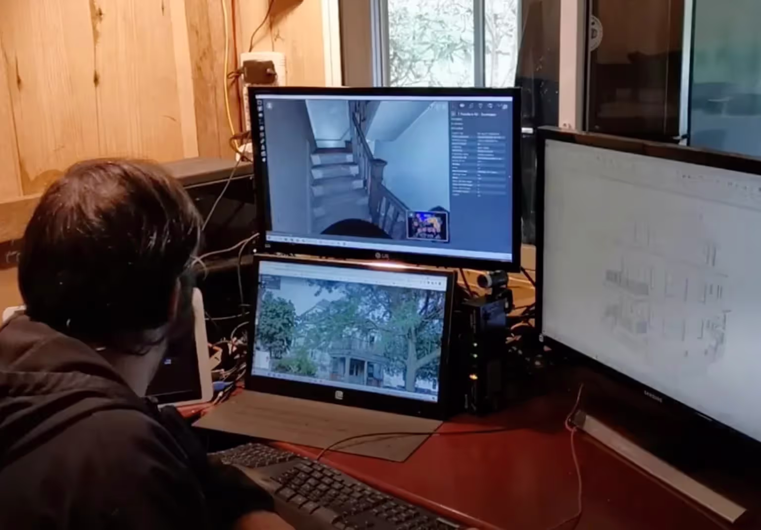
Our 3D Laser Scanning Process


.jpg)
Frequently Asked Questions
What is As-Built Documentation?
As-built documentation is an accurate set of record drawings for a project. They reflect all changes made during the construction process and show the exact dimensions, geometry, and location of all building elements and infrastructure.
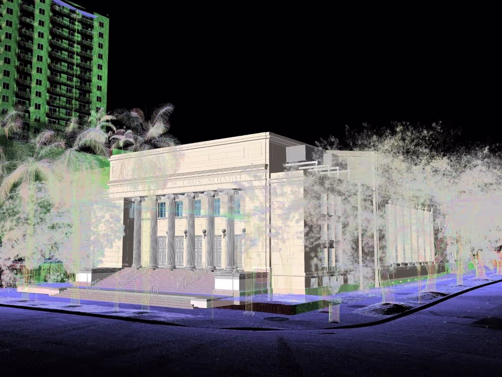
Why Would An Architect Use 3D Laser Scanning?
An architect would use 3D laser scanning services to accurately capture the existing conditions of a building in a point cloud for design and renovation projects. From the point cloud, 2D CAD drawings and a 3D BIM model can be generated to access precise layout and measurements, visualize design changes, and identify potential issues, reducing the risk of errors, ultimately saving time and cost on the project.
How is CAD different from BIM?
CAD is technology and software designed to produce precise technical drawings —replacing manual hand-drawn and drafting techniques with a digital process. CAD is used in many fields, including architecture and engineering, to create accurate and efficient representations of sites.
BIM, or Building Information Modeling, is a process of visualizing a digital representation of a physical asset via the 3D model and includes richer levels of data, including information on materials and equipment. Architects, engineers, and construction managers can track and monitor a building through its entire lifecycle, from initial design to construction, operations, and maintenance. Project teams can collaborate, share information, and monitor project costs using BIM.